|
||||||||||||||||||||||||||||||||||||||||||||||||||||||||||||||||||||||||||||||||||||
Electromagnetic Brake Motor 25 watt |
||||||||||||||||||||||||||||||||||||||||||||||||||||||||||||||||||||||||||||||||||||
We are Manufacturer, Supplier of Electromagnetic Brake Motors from Pune, Maharashtra, India. | ||||||||||||||||||||||||||||||||||||||||||||||||||||||||||||||||||||||||||||||||||||
|
||||||||||||||||||||||||||||||||||||||||||||||||||||||||||||||||||||||||||||||||||||
| Specifications : | ||||||||||||||||||||||||||||||||||||||||||||||||||||||||||||||||||||||||||||||||||||
|
||||||||||||||||||||||||||||||||||||||||||||||||||||||||||||||||||||||||||||||||||||
| Gearmotor Torque Table : | ||||||||||||||||||||||||||||||||||||||||||||||||||||||||||||||||||||||||||||||||||||
| The maximum permissible torque is 80 kg.cm | ||||||||||||||||||||||||||||||||||||||||||||||||||||||||||||||||||||||||||||||||||||
|
||||||||||||||||||||||||||||||||||||||||||||||||||||||||||||||||||||||||||||||||||||
|
||||||||||||||||||||||||||||||||||||||||||||||||||||||||||||||||||||||||||||||||||||
Gear Boxes are sold separately. A Sky blue colored background indicates gear shaft rotation in the same direction; a Brown background indicates rotation in the opposite direction as the motor shaft. The speed of the Gear Motor is calculated by dividing the motor’s synchronous speed (50 Hz; 1500 RPM & 60 Hz; 1800 RPM) by the ratio. The actual speed is 2~20% less than the displayed value, depending upon the load size. Characteristics, specifications and dimensions are subjected to change without prior notice. |
||||||||||||||||||||||||||||||||||||||||||||||||||||||||||||||||||||||||||||||||||||
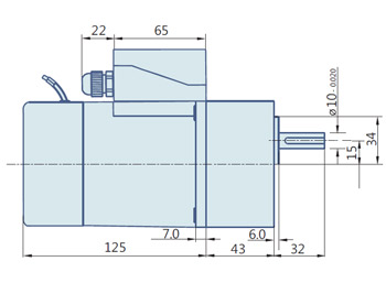
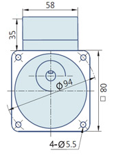
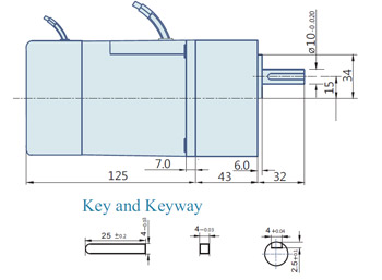
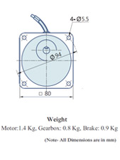
| Dimensions : | ||||||||||||||||||||||||||||||||||||||||||||||||||||||||||||||||||||||||||||||||||||
| 25Watt : AC Geared Motor with Terminal Box | ||||||||||||||||||||||||||||||||||||||||||||||||||||||||||||||||||||||||||||||||||||
|
||||||||||||||||||||||||||||||||||||||||||||||||||||||||||||||||||||||||||||||||||||
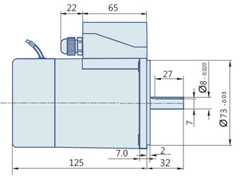
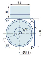
| 25 Watt : Round AC Induction Motor With Terminal Box | ||||||||||||||||||||||||||||||||||||||||||||||||||||||||||||||||||||||||||||||||||||
|
||||||||||||||||||||||||||||||||||||||||||||||||||||||||||||||||||||||||||||||||||||
| 25 Watt : AC Geared Motor With Lead wires | ||||||||||||||||||||||||||||||||||||||||||||||||||||||||||||||||||||||||||||||||||||
|
||||||||||||||||||||||||||||||||||||||||||||||||||||||||||||||||||||||||||||||||||||
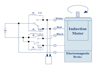
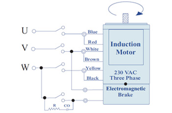
| Wiring Diagram | ||||||||||||||||||||||||||||||||||||||||||||||||||||||||||||||||||||||||||||||||||||
|
||||||||||||||||||||||||||||||||||||||||||||||||||||||||||||||||||||||||||||||||||||
| Wiring diagram for Three Phase Motors | ||||||||||||||||||||||||||||||||||||||||||||||||||||||||||||||||||||||||||||||||||||
|
||||||||||||||||||||||||||||||||||||||||||||||||||||||||||||||||||||||||||||||||||||
| Change the direction of the motor only after it stops rotating, if the attempt is made during rotation, the motor may ignore the reversing command or change the direction after some time. | ||||||||||||||||||||||||||||||||||||||||||||||||||||||||||||||||||||||||||||||||||||
AC Motors | DC Motors | Centrifugal Blowers | Speed Controllers | Linear Actuators
Home | About Us | Products | Download | Careers | Contact Us | Enquiry
Home | About Us | Products | Download | Careers | Contact Us | Enquiry